Overview
The RASS (Radio Acoustic Sounding System), used in addition to the SODAR PCS2000 instrumentation is a reliable and easy to use tool to get a quick information about the atmospheric temperature stratification. Especially in stable conditions the vertical stratification could have a significant influence on the observed ground concentrations of pollutants. The combined SODAR / RASS allows the detection of inversion heights and quantitative measurements of the inversion strength on the basis of the temperature gradients.
The RASS method uses the scattering of vertically emitted radio waves at vertically emitted acoustic waves to determine the vertical profile of the virtual temperature (in very good approximation). Please see further details below in RASS Measurement Principle
Technical Description
RASS Components
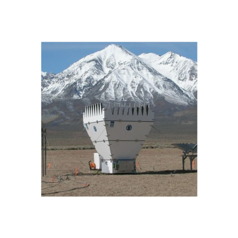
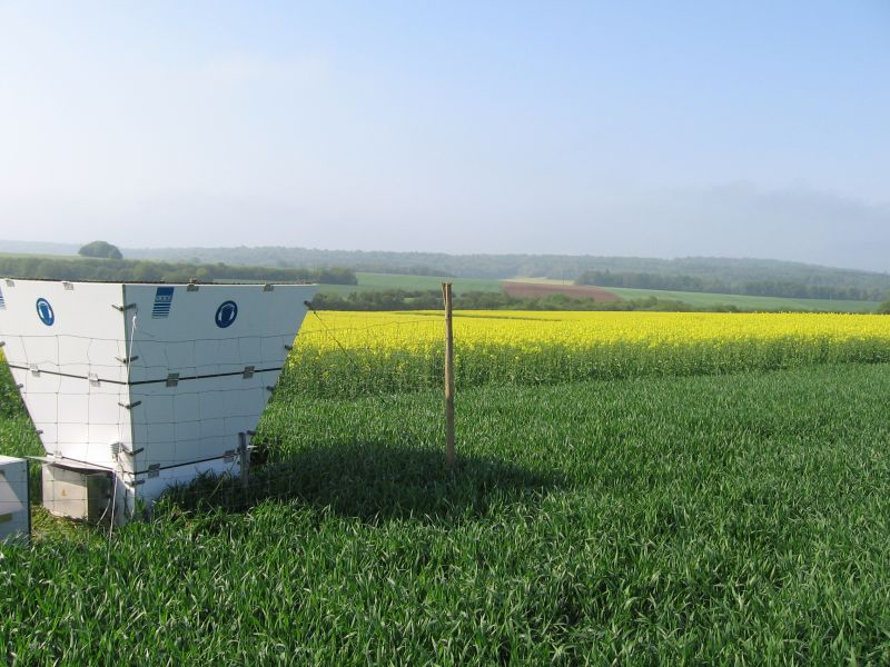
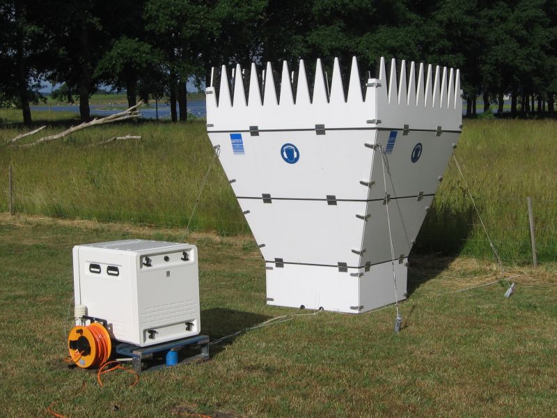
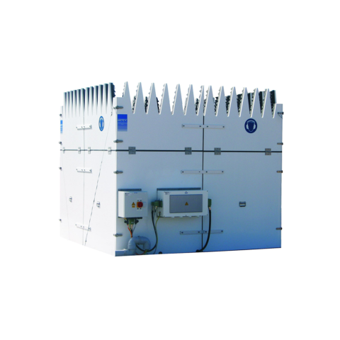
The RASS extension consists of two parabolic antennas, a receiver and a transmitter, plus the electronic RASS components consisting of signal source, power amplifier and receiver.
RASS Measurement Principle
To get the temperature profile in a height range comparable to the SODAR (several hundred meters) the RASS (‘Radio Acoustic Sounding System’) measuring principle uses the reflections of electromagnetic waves at refractivity fluctuations. These required refractivity fluctuations occur in the natural atmosphere. They are generated by its turbulent inhomogeneity but have very different intensities. For this reason the RASS uses artificial refractivity fluctuations generated by acoustic pulses from the vertical antenna of the SODAR system. This insures a reasonable intensity at a known distribution of wave numbers. RADAR frequency and acoustic frequency must meet the Bragg condition to guarantee a constructive interference. This means that the wavelength of the acoustic waves is half of the wavelength of the electromagnetic waves.
Because the acoustic frequency may vary strongly with the time and the height, which is caused by influence of temperature, the RASS does not use only one single acoustic frequency but a signal covering a specific bandwidth. The mean frequency of the transmitted acoustic signal is adjusted to the measured ground temperature. For an electromagnetic frequency of 1274 MHz (ëe = 0.23 m) this corresponds to an acoustic wavelength of ëa = 0.115 m resulting in a typical mean frequency of 2900 Hz (depending on temperature). Similar to the measuring principle of the SODAR the reflected RADAR waves will show a frequency shift in comparison with the transmitted waves, which is a measure of the sound velocity. The air temperatures in the different heights can be derived from the sound velocities which must be corrected for the vertical wind measured by the SODAR. The analysing of the received signal is done by the same algorithms as described above for the SODAR.
The electromagnetic transmitter is running in CW2-mode. The used bandwidth is very small therefore and only limited by the frequency stability of the oscillator. Due to the CW-mode the RASS uses separate vertical aligned electromagnetic antennas for transmitting and receiving.
The effects of wind on the acoustic waves of the RASS extension
As the acoustic waves, while propagating upwards through the atmosphere, can be shifted by the horizontal wind the location of the reception spot at the ground surface moves with the height range the signal originates from. So during strong wind situations the spot can be shifted very rapidly out of the reception area. This displacement is the most limiting factor in RASS technology. It can be compensated by using not only a single acoustic source, but a number of acoustic sources distributed around the radar antennas and selected for operation according to the observed wind direction. This will significantly increase the price for the RASS extension, but is at least a way to improve the data availability coverage, especially for heights above 300-400 m.
A further choice out of the dilemma with sound wave shift is the usage of bigger radar antennas which will also increase the antenna aperture for both, emission and reception. So, the usage of bigger radar antenna can be a more cost efficient way and the frequency of the radar part of the RASS can be changed to 480 MHz. The lower frequency offers one more advantage: the atmospheric absorption of acoustic energy decreases with decreasing frequency, so the scattering cross section will be higher for the scattering process.
1290 MHz versus 480 MHz RASS
From the experiences of long term operation with both systems we can state that a 80% height coverage for the RASS will be provided for 300 – 400 m in wind situation below 5 m/s for the 1290 MHz RASS and 600-800 m for the 480 MHz RASS. In combination with high powered wind profiler the RASS range can be extended up to 1000 m or even 3000 m but with much higher costs and poor height resolution (factor 5-10 in both, price and resolution). As environmental monitoring of dispersion parameters acts on emissions near the surface or at height up to 100-200 m the dominating parts in the dispersion of pollution will always be the wind and temperature profile within the first hundred meters, i.e. the typical height range of a system should be about 300-500 m. However, a consideration of the 1290 MHz RASS versus the 480 MHz RASS is recommended. For further information on a 480 MHz RASS system please contact Biral.
Operation permission and national frequency licence
It is the obligation of the operator of a RADAR system (or RASS) to apply for the required national frequency licence. Due to the world wide standardisation of these radar frequencies this is more or less just a formal act, but it has to be done. Biral / Metek explicitly confirm all assistance to help the customer with this procedure and to supply all required information about the RASS system.
Specifications
Antenna
Transmitter
Receiver
Other Products
Related Products
Sales & Support
Contact Biral for more information
To find out more about this instrument or to discuss your application requirements please do not hesitate to contact Biral.
- Complete our enquiry form
- Email enquiries@biral.com
- Telephone +44 (0)1275 847787
After Sales Support
Biral offers free advice and technical support for the lifetime of the instruments we sell. Once you have purchased the unit you can always contact us for help using the links on our Service Support page.
Enquire about this product
"*" indicates required fields